Raman spectrograph version 2: construction.
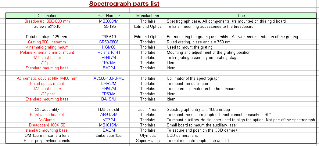
| The details of the construction of the Raman spectrograph are given on this page. The parts list with manufacturer name and part numbers are reported on the table below. This spectrograph can be assembled with commercially available components as seen on the photographs below. The only thing to build is the cabinet, home made with black polyethylene panels. To mount the optical components I used an optical breadboard manufactured by Thorlabs. This board greatly facilitates the positioning of the components and allows easy modifications for testing purposes. It is rigid and thus maintains quite well the position of the optical parts. It is worth the expense ! The grating is mounted on a very stable rotation stage from Edmund optics with a kinematic mount and holder for an easy adjustment of the mechanical positioning. The entrance slit assembly is fixed on a rigid plastic panel secured at 90° of the breadboard with precision right angle brackets. The collimator is mounted with post and post holder as shown. A baffle is installed in front of the collimator to prevent the overloading of the entrance optics by the reference neon light which enter the spectrograph with a cone angle wider than f/8. The Olympus OM 135mm lens is mounted on the camera with an adapter OM bayonet to T2 thread. To prevent spurious light coming into the spectrograph, the bottom of the breadboard and the corners of the case are covered with black tape. A black plastic cover is secured on top with long treaded rods and thumb screws.
|
|
|
|
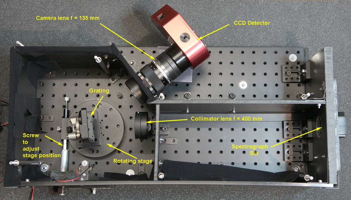
View of the spectrograph top cover removed.
|
|
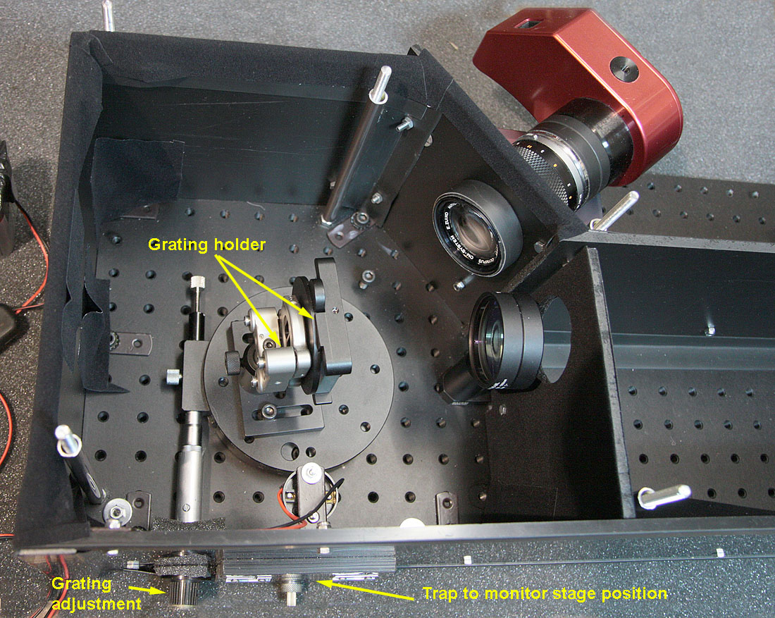
Details of the spectrograph showing grating mount, lenses and camera. There is a trap opening to the right of the grating adjustment knob with a 3Volts bulb at the top to illuminate the rotating stage scale. This allows an easy adjustment of the wavelength range without too much hardware.
|
|
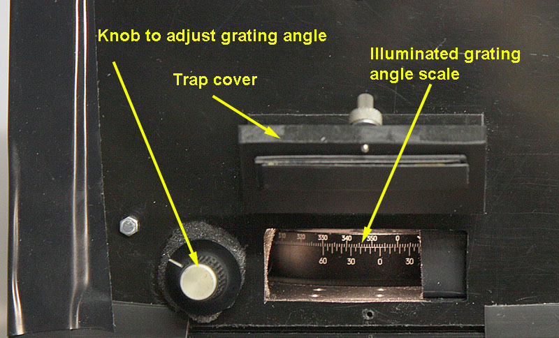
Trap opened with illuminated grating angle scale and vernier and adjustment knob. Grating adjusted here at 6.7° for a 630 nm to 730 nm wavelength range.
|
|
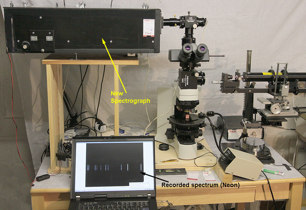
New spectrograph installed in the Raman microscope assembly. This picture illustrates the complete implementation of the Raman microscope with the new spectrograph replacing the H20 monochromator (click here to see previous design). The spectral acquisition is performed by a laptop computer. On this picture, a reference neon light spectrum is shown. The rest of the equipment remains the same.
|
Previous Page Next page Raman Main Page