Raman Microscope beam splitter
|
|
|
|
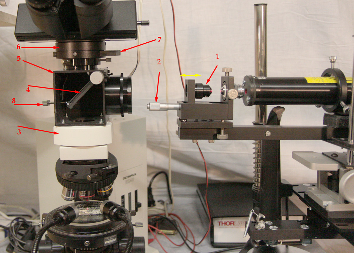
The picture above shows in more details the beam splitter assembly with cover removed and the laser head with the modified spatial filter. The shape of the beam can be adjusted by moving one of the objective (along yellow arrow on the picture) with the help of the micrometric screw (2). The beam splitter and filter are inserted directly into the microscope column so they require special attention to avoid loosing image quality. This assembly is composed of three mechanical parts:
The 3 components described above secured together can be considered as a Raman head restricted to one laser wavelength. If the laser line is to be changed, then this head should also be replaced or adapted with new optical parts. The head can be easily removed from the microscope as both end components have the Olympus mechanical connectors. Even if the height of this head is outside the specification of Olympus for the maximum thickness of the accessories which can be introduced into the microscope column, I have not noticed any important image degradation. Of course for critical imaging or quality photographs, it would be best to remove this Raman head from the microscope. The telescope flip mirror has been modify by removing first the mirror positioned on the rotating plate (4), drilling a large hole in that plate and holding the beam splitter in place with a plastic sheet and screws. The precise angle between the splitter and the laser beam can be adjusted with the blocking screw (8). The adjustment of the angle between the dichroic mirror and the laser beam is done by monitoring the transmitted laser line which must reach a minimum for proper positioning. If a classical beam splitter is used, its positioning is not so critical but much light power is lost: 50% of the light will be lost on each passage through the splitter it means that for two crossings, 75 % of the light is lost. The beam splitter can easily been swung out of the light path to get a full color image of the specimen. The spectral curve of the dichroic plate from http://www.edmundoptics.com/products/ is reproduced below. Above the beam splitter, we can see the removable laser long pass filter (7) to avoid the high intensity laser line reaching the detector. This filter is removed from the light path when adjustment of the optics is necessary ( for instance positioning of the laser spot on the entrance slit of the spectrograph ) or for image examination.
|
|
|
|
The spectral curve of the dichroic plate has a minimum transmittance at
the laser wavelength and pass the light a few nanometers above laser
line. The band pass of this filter from 636 to around 1000nm is wide
enough for Raman spectroscopy: 4000cm-1 corresponds to about 850 nm for
a laser line at 632.8 nm.
|
|
|
Spectral curve of the laser long pass filter from Edmund optics . Note that the laser blocking power of this filter is much higher than the dichroic plate described above and that the curve at 635 nm has a much steeper slope. This kind of filter is also named a "razor blade filter". So the dichroic beam splitter cannot be used alone without this additional long pass filter. |
Previous page Next Page Raman Main Page