Scintillators and FTLAB Signal Conditioning.
| The signal pulses out of an SIPM component must be amplified and shaped to be used by a counting system or a pulse height analyzer. As I have built several detectors, I have tried different electronics as the amplitude and the width of the pulses could be different according to the detector.
|
 |
|
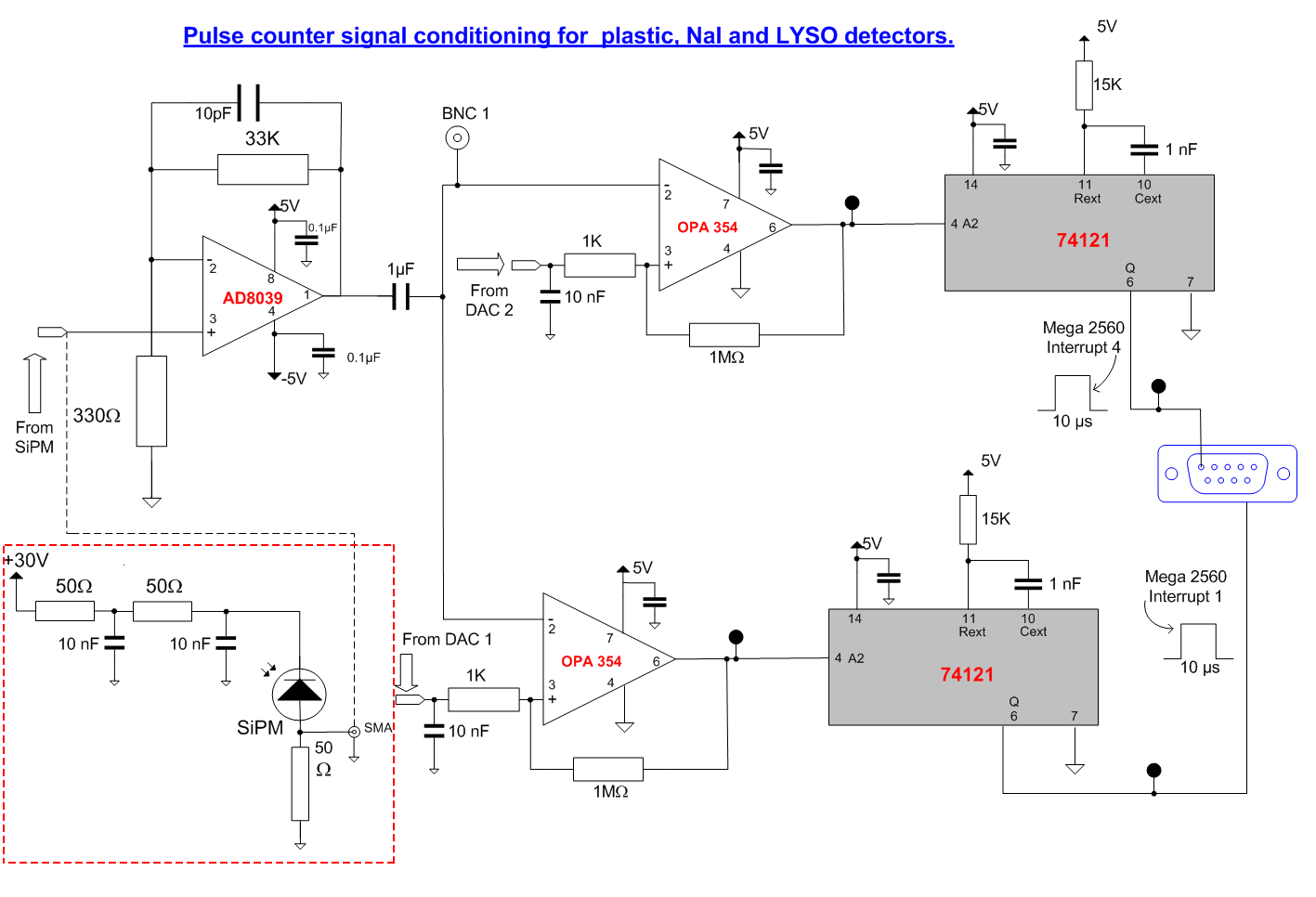
Pulse counter conditioning circuit. The SiPM polarization circuit is on the bottom left of the figure enclosed in a red rectangle. The SiPM equivalent circuit is represented by a reversed polarized photodiode. In fact the SiPM is a network of several thousand avalanche photodiodes. The SiPM should be powered by a 28 to 30V supply according to the pulse height out of the scintillator. In my design, I generally use three 9V batteries in series with an additional 1.5V battery which can be switched ON and OFF. The filter made of two 50 ohms resistors and two 10 nF capacitors is recommended by the SiPM manufacturer. When a light pulse is detected by the SiPM, a current pulse pass through it and the 50 ohms resistor in series. This creates a voltage pulse which is fed to the input of an AD8039 amplifier through SMA connectors and cable. The first AD8039 is a high gain preamplifier. The amplified signal is sent to both OPA354 op amps mounted as Schmitt triggers. The OPA354 comparator transforms the analog pulse of variable amplitude to a 0-5V pulse of variable width according to the height of the input pulse. The OPA354 comparator is acting as a discriminator: if the pulse amplitude is grater than the voltage applied on pin 3 of the amplifier, the digital pulse at the output pin 6 is passed to the counter. If the pulse voltage is lower than the discriminator reference, it is not counted. The Schmitt trigger has a small hysteresis to avoid spurious peaks. The reference voltage at pin 3 is coming from a small digital to analog converter (DAC) connected to the Arduino microcontroller. After several tests with Arduino and a pulse generator, I came to the conclusion that a 10 Ás digital pulse was the minimum pulse width required to avoid a lost of counts by the microcontroller. It can thus count to 100000 pulses per second which is plenty enough to measure the radioactivity of natural rocks. The time variable pulses coming from the OPA354 are sent to a 74121 TTL monostable multivibrator whose output is directly connected to an interrupt line of the Arduino. The 15K resistor and the 1 nF capacitor transform a variable input pulse to a 10 Ás pulse. The system uses a two channels counter with 2 comparators, 2 monostable IC and 2 interrupt lines. As the system uses two discriminators, if the pulse amplitude is higher than the second discriminators, 2 interrupts are generated close to each other. The program uses the rising part of the pulse to generate the first interrupt and the falling part of the second digital pulse to generate the second interrupt as indicated on the schema above. This method has also been tested up to 100 kHz.
|
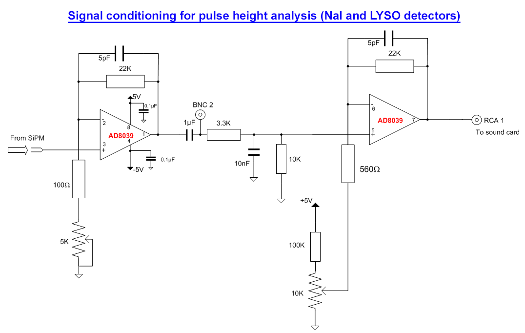 |
| Pulse height analysis with NaI and LYSO detectors. The multi channel analyzer (MCA) is the combination of the PC sound card and the Theremino MCA program (https://www.theremino.com/en/downloads/radioactivity). The sound card has a bandwidth of 200 kHz but for a good pulse analysis by the software, the pulse width should be adjusted between 50 and 100 Ás. The pulses from NaI, plastic and LYSO detectors are much narrower than this value. The input pulses must thus be amplified and shaped to a much wider width before they can be processed by the MCA. The first AD8039 op amp is mounted as a variable gain preamplifier which can be adjusted by the 5K potentiometer. The second AD8039 is the pulse shaper. It is mounted as an integrator with 3.3K resistor and 10 nF capacitor to produce a pulse width of about 50 ÁS (see the tests page). The 10 K potentiometer can adjust the position of the baseline.
|
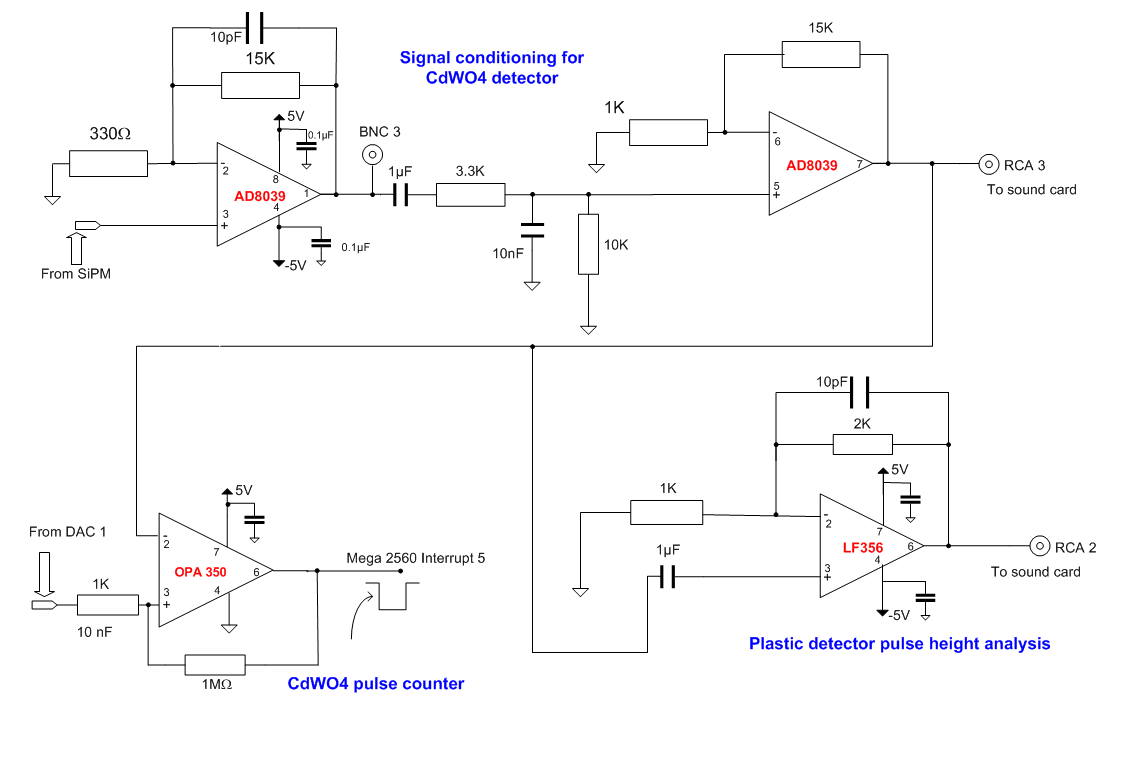 |
| CdWO4 signal conditioning. The CdWO4 scintillator has a much longer decay time than the NaI or LYSO detector in the 10 Ás range so the conditioning electronics for counting and pulse height analysis is different. The preamplifier is similar with a fixed gain but a shaping second stage is necessary before the OPA350 comparator to avoid that spurious peaks are sent to the counting system. (for an illustration of pulse shapes see the tests page). The CdWO4 preamplifier and shaper can also be used for pulse height measurements with the plastic scintillator, a second amplification has been added (LF356) to bring the signal in the right range for MCA.
|
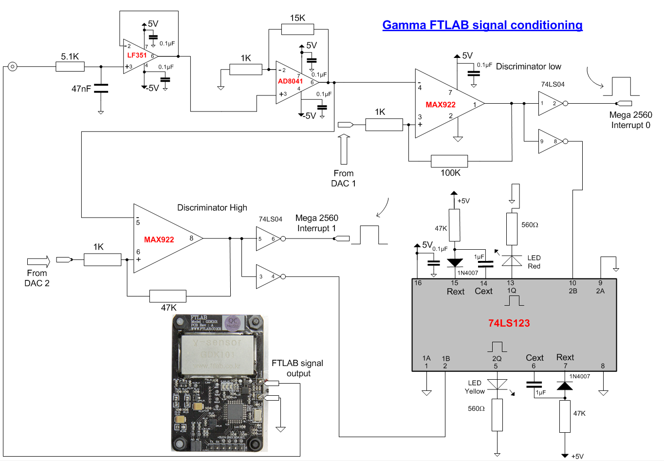 |
| Gamma FTLAB module. The gamma FTLAB is a PIN diodes network mounted on a small PCB. It has a signal conditioning and microcontroller on board. It can be connected to an Arduino microcontroller to read the gamma counts directly. The amplified and conditioned signal is also available at an analog output for an external processing. The circuit above describes the conditioning of these external pulses for counting with Arduino interrupts. Direct comparison of internal and external counting is thus possible. The signal is shaped and amplified by a two stage circuit. The integrated circuits used for this purpose are not high speed models because the output pulses width of the FTLAB is much larger then NaI and LYSO scintillators (see the tests page for an example). The first stage is the integrator (LF351 mounted as a voltage follower) and the second stage, AD8041, is the voltage amplifier. The 2 comparators MAX922 transform the analog pulses whose amplitude is greater than the reference voltage of the 2 DAC's into digital pulses sent to the interrupts lines of the Arduino Mega 2560. In this case, the digital pulse is wide enough to be directly counted by the microcontroller. Again the rising edge of the pulse from the low level discriminator and the falling edge from the high discriminator are used to generate the interrupts. The 74LS123 double monostable multivibrator generates a LED flash each time a pulse pass through the discriminator. The count rate of the FTLAB detector is low enough so the single LED pulses are easily detected. The LED indicator is not used with the scintillator detectors because the pulse rate is much higher in that case.
|
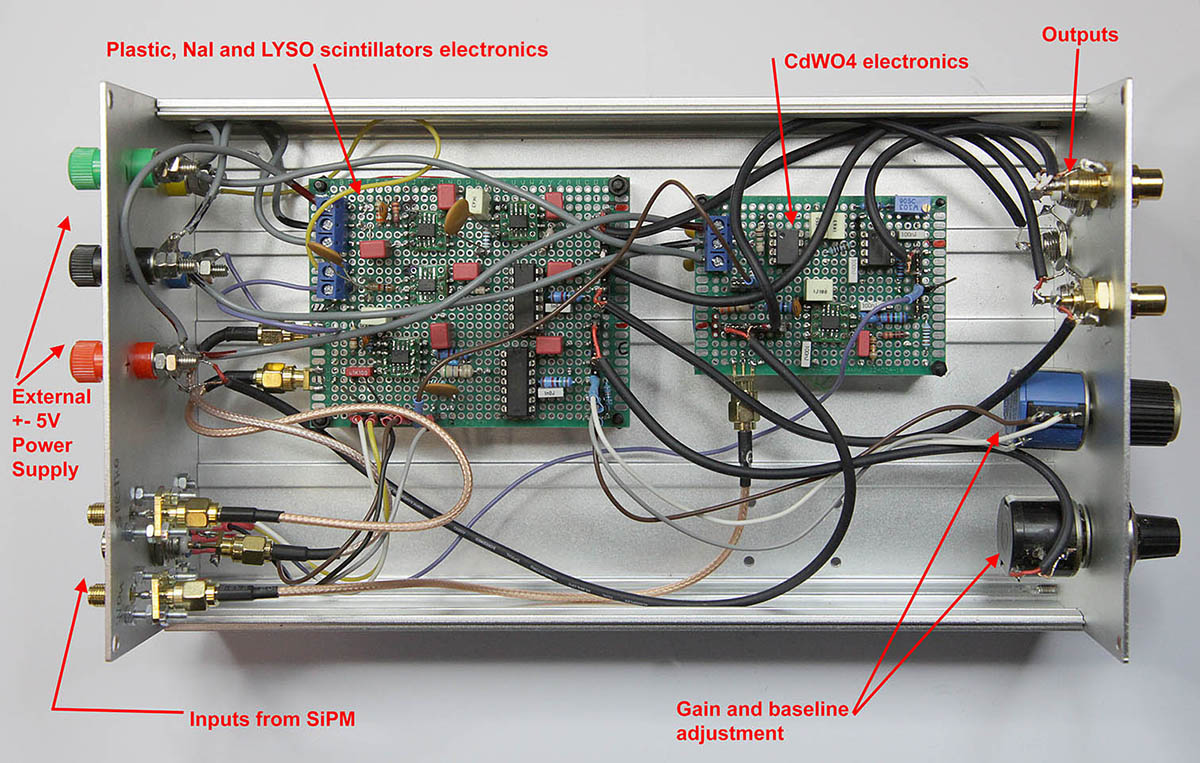 |
| Picture above gives the details of the layout of the signal conditioning for NaI, LYSO, Plastic and CdWO4 scintillators. The +- 5V power supply is external to the metal cabinet to reduce the noise. The FTLAB will be shown on next page.
|