Radioactivity measurement hardware
 |
|
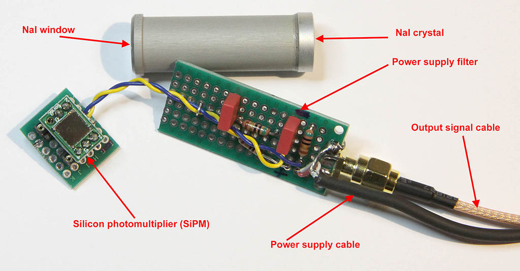
| The three parts of the Sodium Iodide detector: - on top the NaI crystal surrounded by a humidity protection enclosure with a front window. NaI is very sensitive to water vapor. - on the left the SiPM component on a small PCB. It's front face is glued to the crystal window. I have used oil for microscopy to make the optical contact with the detector. The SiPM is the MicroFC−60035−SMT 6mm from ON semiconductor. It came on a MicroFC−SMA evaluation board as seen on the image above. - on the right the power supply filter. The SiPM must be polarized by a 30V supply. I have used three 9V batteries in series (this makes 28.5V with new batteries) and a 1.5V small battery in series which can be switched ON and OFF. A double filter (50 ohms resistors with 10 nF capacitors) reduces the noise of the power supply. The SiPM is equivalent to a reversed polarized diode as can be seen on the schematics on next page, the output signal is taken across a 50 ohms resistor via an SMA connector and cable. The signal is sent to a preamplifier and shaper electronics described on next page. For the details about SiPM see the brochure of ON semiconductor at the following URL: https://www.onsemi.com/pdf/datasheet/microc-series-d.pdf To know the details of how radiation detectors work, the book : Radiation Detection and Measurement by Glenn F. Knoll Wiley is a must.
|
|
|
|
|
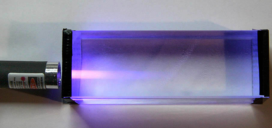
| Plastic scintillator. When the material is illuminated with a 405 nm laser, a violet fluorescence appears. The scintillator is much larger than the SiPM so a big amount of the luminescence is lost. The SiPM is glued on the left side at the laser position.
|
|
|
|
|
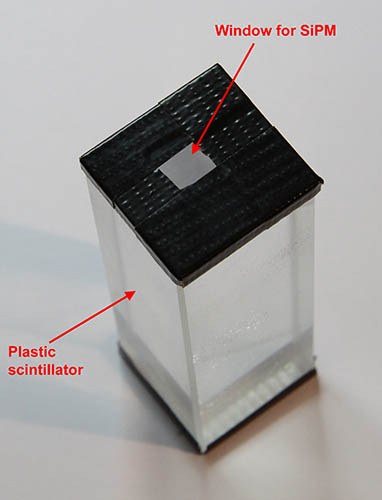
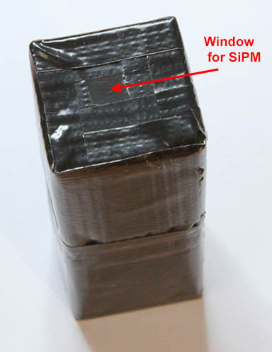
| The plastic scintillator must be covered with black tape to avoid spurious light. The left picture shows the window cut in the black tape where the SiPM must be positioned. The scintillator is first wrapped in a first layer of white Teflon before being covered with the black tape. The tape used has an inner face of white material. On the right, the detector fully covered with the tape. SiPM is then glued on the small top window.
|
|
|
|
|
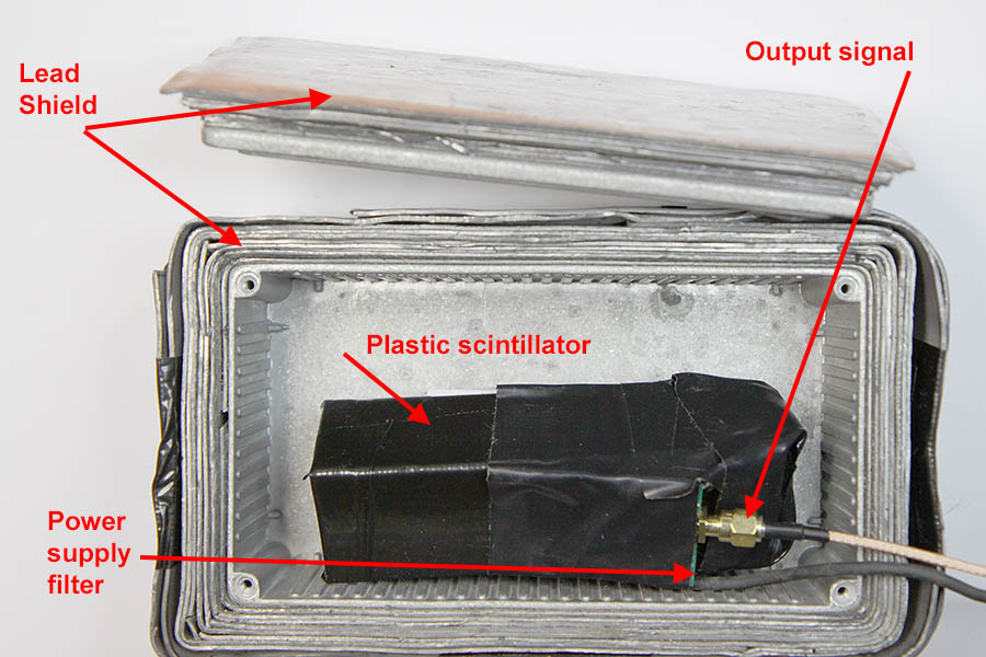
| Picture above shows the finished plastic detector equipped with the same filter as NaI scintillator. For low level activity measurement, the background of the detector must be kept as low as possible. Natural radioactivity from the high atmosphere and the building materials is also measured by the detector. To reach the low level background, a lead shielding is used. The detector and material to be analyzed are placed in an aluminum box surrounded by a few layers of lead. The box is closed by a lead protected lid. The small box itself is introduced into another metal box (not shown) again lined by another layer of lead. The total thickness of the lead shield is around 2 cm. This is not enough to really reduce the background to a very low level, it is only a compromise between weight, cost and performance. The inner box must be cleaned after each measurement to avoid contamination by an active mineral in particular before a background measurement. The background should be measured regularly to avoid fluctuations during the day or a variation in the detector sensitivity in the long run.
|
|
 |
|
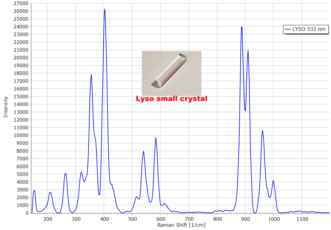
| The LYSO crystal used is very small (picture above), 2 cm long and 4 mm thickness. Two crystals have been glued side by side and the SiPM positioned on the side face. Again the crystals are covered by a Teflon tape and a black tape. The detector is again equipped with the same filter. The Raman spectrum of the lutetium-yttrium silicate has been recorded, it is similar to the literature spectrum. (PHYSICAL REVIEW B 76, 054112 ,2007)
|
|
 |
|
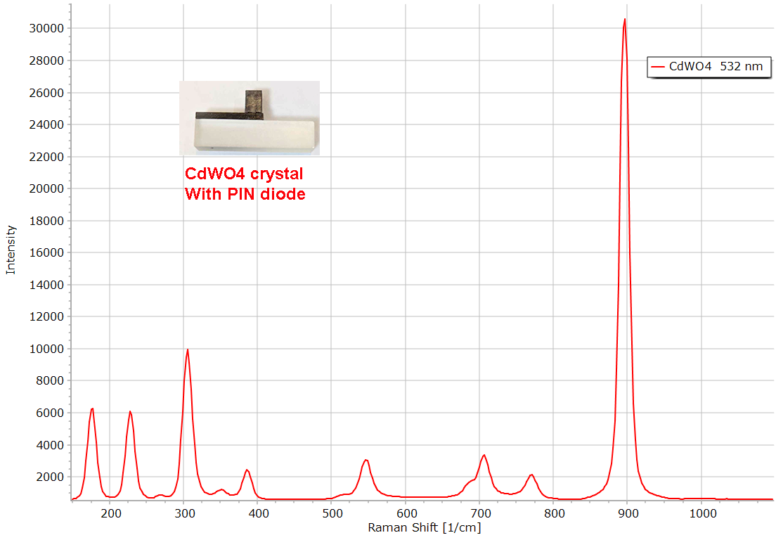
| Cadmium tungstate from Russia. The crystal is equipped with a PIN diode by the manufacturer. I did not use this diode for the measurements, I rather fix an SiPM on the lateral face as usual and enclose the detector in white Teflon and black tape. The recorded Raman spectrum of CdWO4 is reproduced above.
|
|
|
|
 |
|
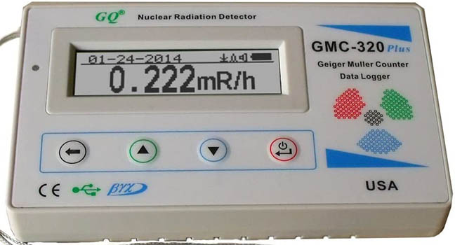
To compare the results of my scintillators to other detectors, I have connected the gamma FTLAB on the left (network of PIN diodes) to an Arduino micro-controller. The digital output and analog pulses of this FTLAB board have been used. A low cost commercial Geiger counter on the right has also been tested.
|
|
