Conoscopy of Uniaxial Minerals.
1. Conoscopy optics.
|
Figure1. Conoscopy Optics |

Conoscopy is the examination of the interference figures in the focal plane of the microscope objective lens produced by an anisotropic crystalline section viewed under convergent light illumination and crossed polars. Figure 1 is a simplified diagram of the optical arrangement. The crystal is illuminated through a high numerical aperture condenser which creates the convergent light beam. A high numerical aperture objective lens collects as much light as possible: the wider the angle, the wider the image. A polarizer is placed under the condenser and a crossed analyzer in the microscope tube above the objective as usual.
A parallel beam of direction D1 is focused in the objective focal plane at a point P1. The same is true for another direction D2 focused at point P2 due to the properties of the focal plane of a lens. Each point of the focal plane thus receives the light of one direction only (if the lens is a perfect one). If we can examine this focal plane, we could infer the properties of each point of the figure from the properties of the associated light direction. Thus, conoscopy is not looking at the image of the crystal produced by the objective lens in the usual way with normal eyepiece (orthoscopic image) but at what happens in the focal plane of the objective lens. To see this image, three methods could be used:
The Bertrand lens is a retractable lens placed in the microscope tube of the petrographic microscope. It is the easiest way to observe conoscopic image but the cost can be rather high depending on the microscope.
Direct View: remove the eyepiece and look through the tube to see a small interference image. The cost is zero but the image is very small and can't be photographed without additional optics.
Phase contrast telescope: this is a special eyepiece used to align the phase contrast rings. It is generally much less expensive than a dedicated Bertrand lens and allow to see a magnified image. It can also be used to photograph the images. All the conoscopic pictures throughout this site have been made with this device.
2. Index of refraction. Optical indicatrix.
|
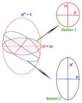
Figure 2. Optical indicatrix |
In anisotropic crystals, the variation of refractive index
with direction of incident light can be represented by an ellipsoid called
indicatrix. For cubic crystals, the indicatrix is a sphere. For uniaxial
crystals, it has a circular symmetry around the optical axis and for
biaxial crystals it is a general ellipsoid with only 2-fold symmetry. To
determine the refraction indices and vibrations directions of a light
beam moving through a crystal, consider the section in the ellipsoid
perpendicular to light direction. In figure 2, two sections have been
made:
Section 1 is a circle, it is the section perpendicular to the optic axis. Section 2 is an ellipse with indices n and n'. In uniaxial crystals, every section contains index n called ordinary index (w) and a second index with magnitude between w and the other ellipsoid axis e (extra - ordinary index) |
3. Examination of crystals under a parallel beam of light.
In next section, we'll explain the features of the convergent light figures mainly using the results of the examination of crystals under a parallel beam of light. Let us now summarize those results :
If the condenser of the microscope is lowered or the top lens removed, the sample can be illuminated with a light beam nearly parallel to the microscope axis. In figure 1, the green beam illustrates this situation. This beam is focused at the center of the conoscopic image, thus the center of the interference image is a concentrated view of the orthoscopic image and it has the same extinctions and colors. If our parallel light beam is monochromatic, extinctions can arise for different reasons:
0. No crystal is present on the microscope stage: this is the trivial situation, no light can pass the analyzer crossed with the polarizer.
1. A cubic crystal or a section of a uniaxial crystal perpendicular to the optic axis or a section of a biaxial crystal perpendicular to one of the optic axes: as seen above, those sections have no optic anisotropy (circular section through the indicatrix) and do not change the polarization of the light.
2. Random section of uniaxial or biaxial crystal with the main ellipse section axes oriented along polarizer and analyzer: only one light beam is moving through the crystal section along polarizer direction and is extinguished by analyzer.
3. Random section of uniaxial or biaxial crystal with random orientation: in this case, the original light beam is split in two beams moving in the crystal at different speed inversely proportional to the section ellipse refraction indices. The two beams normally interfere after the analyzer. An extinction can occurs if the beams are 180° out of phase. This happens if the retardation of the section is a multiple of the wavelength of our monochromatic beam: d.(n' - n") = k.l where d is the thickness of the crystal section, n' and n" are the indices of refraction obtained by sectioning the crystal indicatrix perpendicularly to the light beam, k is an integer number and l is the wavelength of the beam. (n' - n") is the birefringence of the crystal section and d.(n' - n") is the retardation of that crystal section. If we now illuminates our crystal with white light, extinction occurs for one or several wavelength depending on the thickness of the crystal. This produces color effects known as Newton color scale. One example of such a scale coming from a conoscopic image of calcite is reproduced in figure 2.
|
Figure 3. |

4. Uniaxial conoscopic figure.
|
Figure 4. Simplified diagram of uniaxial conoscopic image formation. |

Consider in figure 4, a crystal section of a uniaxial material perpendicular to the optic axis. Three different directions of light have been represented in the figure with corresponding section in the indicatrix. For each direction, the distance covered by light in the crystal is different, being minimum for direction perpendicular to the crystal section. Moreover, the birefringence is also direction dependent according to the section in the indicatrix perpendicular to light direction. To summarize all this let's say that the retardation depends on the light direction.
The red section in indicatrix is a circle. The associated light beam being parallel to optic axis is focused at the center of conoscopic figure (point A). This point is always dark because birefringence for this direction is zero. ( condition 1 of section 3 above).
The blue section is more inclined, its indexes are parallel to polarizer and analyzer main directions. The light focuses on point B, the indexes are now w and e'. There is also extinction for this beam due to condition 2 of section 3 ( indices parallel to polarizer and analyzer).
The green section is similar to the blue one with a greater index e''. Point C on the interference figure should be dark for the same reason.
|
Figure 5. Uniaxial conoscopic image perpendicular to the optic axis. |
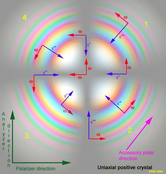
Let's examine now the complete uniaxial figure perpendicular to the optic axis. By a similar reasoning as in figure 4, we can draw on this figure the orientation of refraction indices. As the indicatrix has circular symmetry around the optic axis, the interference figure should also have a circular symmetry around the pole of the optic axis (center of figure). As can be seen in figure 5, the ordinary index w is always tangent to the concentric circles and the extraordinary indices e' are always radial with a magnitude increasing from center to periphery. The value of this e' index is constant on a circle.
All the points with indices parallel to the directions of polarizer and analyzer are dark due to condition 2 above. They form a dark cross called the isogyre. The isogyre is invariant by rotation because for symmetry reason the projection of the indices of refraction is also invariant by rotation.
All the points on a circle have the same indices of refraction with different orientations. For symmetry reason, the optical path in the crystal section is also constant because the angle of the incident light is the same for al points on a circle, so the retardation is constant. From condition 3 above, it can be seen that an extinction could occur for all the points of a circle for the same wavelength of the light. This figure is called the isochrome. We'll examine further on next page the behavior of these extinction rings to explain the colors fringes observed.
[Next Page] [Conoscopy main page] [Home]